Showing posts with label ZFS Storage. Show all posts

Friday, October 31, 2014

Disaster Recovery of WLS Applications on Exalogic

Introduction

For many years Oracle Fusion Middleware based on WebLogic server has been capable of being used to provide high availability, fault tolerance and disaster recovery capabilities.  This has been documented as part of the Maximum Availability Architecture whitepapers. Follow this link for all the MAA documentation or follow this link to go directly to the Fusion Middleware Disaster Recovery architecture documentation.

Exalogic/Exadata provides an ideal platform on which these architecture can be realised with all the advantages that come with using Oracle Engineered systems.

This blog posting gives a very high level overview of the principles used in implementing active/passive DR for a fusion middleware application.  Much of the activity involved from an application perspective is identical irrespective of the deployment being on physical or virtual hardware.  In this article we will have a slightly deeper dive on how the Exalogic ZFS storage appliance is used to enable the DR solution.

Basic principles involved in setting up FMW DR

The basic tenet of deploying an application is to follow a set of rules during the deployment/configuration of the application which will make it simple to start the application up on the DR site.  The setup should be:
  1. Deploy all tiers of the application ensuring:-
    1. In the primary environment a set of hostname aliases are used for all configuration, these aliases not linked to the specific host and all configuration in the products specify these names rather than actual IP addresses.
    2. The binary files and application configuration  (normally the domain homes) are all located as shares on the ZFS appliance and mounted via NFS to the Exalogic vServers.
    3. Critical application data that must be persisted goes into the Database.  Specifically thinking of the WebLogic Transaction logs and the JMS messages.  (We will use the Oracle Data Guard product to ensure critical data is synchronously copied to the remote site)
    4. Keep the configuration in the Operating System to an absolutely minimum possible.  Probably no more than /etc/hosts entries and if needed specific service startup commands.  Other OS configuration should be built into the templates used to create the environment in the first place.
  2. Create mirror vServers on the DR site.
    1. These vServers will be used to host the production environment when DR has occurred.  The same minimal OS configuration should be present in this site.  To save time in DR the servers can be started up or they can be started on-demand at DR startup.  If already running then ensure that the application services are all shutdown.  The hosts files must have the same hostname aliases in it that the primary site has but obviously they will be resolving to different IP addresses.
  3. Create a replication agreement for all the shares that host the application binaries and domains.
  4. When DR is to happen   (ignoring DB)
    1. Break the replication agreement
    2. Export the replicated shares so that they can be mounted.
    3. Mount the replicated shares in exactly the same location on the DR vServers
    4. Startup the application on the DR environment
    5. Test and if OK then redirect traffic at the front end into the DR service.
Obviously this is somewhat simplified from most real world situations where you have to cope with managing other external resources, lifecycle management and patching etc.  However the approach is valid and can be worked into the operations run book and change management processes.

All these steps can be automated and put into the control of Enterprise Manager such that the element of human error can be removed from the equation during a disaster recovery activity.

Using the ZFS Storage Appliance for Replication

From the application perspective a key function lies with the NAS storage which has to be able to copy an application from one site to another.  The ZFS Storage appliance within an Exalogic is a fantastic product that provides exactly this functionality.  It is simple to set it up to copy the shares between sites.

Setup a Replication Network between sites

The first activity required when wishing to perform DR between two sites is to create a replication network between the ZFS appliance in both Exalogic racks.  This can be done using the existing 1GbE management network that already exists, however this is not recommended as this network is not fault tolerant, there being only one 1GbE switch in the rack.  However on the ZFS appliance there are two 1/10GbE network connections available on the back of each storage head (NET2 & NET3).  By default one connection goes into the 1GbE switch and the other is a dangling cable, thus two independent routes into the data centre are available.  If a longer wire is required to connect then it is possible to disconnect the existing ones and put in new cables.  (Recommendation - Get Oracle Field Engineers to do this, it is a tight squeeze getting into the ports and the engineers are experts at doing this!)

Once each head is connected via multiple routes to the datacenter and hence on to the remote Exalogic rack then you can use link aggregation to combine the ports on each head and then assign an IP address which can float from head to head so it is always on the active head and hence has access to the data in the disk array. 

Replicating the shares

Having setup the network such that the two storage appliances can access each other we now go through the process of enabling replication. This is a simple case of setting up the replication service and then configuring replication on each project/share that you want coped over.  Initialy setup the remote target where data will be copied to.  This is done via the BUI, selecting Configuration, and then the Remote Replication.  Click on the + symbol beside "Targets" to add the details (IP address and root password) of the remote ZFS appliance.

Adding a replication target
Once the target has been created we now setup the project/share to be replicated.  Generally speaking I would expect a project to be replicated which means that all the shares that are part of the project will be replicated, however it is possible to replicate at the share level only for a finer granularity.
To setup replication using the BUI simply click on the Shares and either pick a share or click on the Projects and edit the project level.  There is then a replication sub-tab and you can click on the "+" symbol to add a new "Action" to replicate. 

Replication of a project
Simply pick the Target that you setup earlier in the Remote Replication agreement, pick the pool - which will always be exalogic - and define the frequency.  Scheduled can be down to every half hour or Continuous means that it will start a new replication cycle as soon as the previous one completes.  There are a couple of other options to consider, Bandwidth limit so that you can prevent replication swamping a network, "SSL encryption" if the network between the two sites is considered insecure and "Include Snapshots" which will copy over the snapshots to the remote site. 

Obviously the latter two options have an impact on the quantity of data copied and the performance is worse if all data has to be travelling encrypted.  However, after the initial replication only changed blocks will be copied across and given that the shares are used primarily for binaries and configuration data there will not be a huge quantity flowing between the sites.

Process to mount the replica copies

Having completed the previous steps we have the binaries and configuration all held at the primary site and a copy on the remote site.  (Although bear in mind that the remote copy may be slightly out of date!  It is NOT synchronous replication.)  For DR we now assume that the primary site has been hit by a gas explosion or slightly less dramatic we are shutting down the primary site for maintenance so want to move all services to the DR environment.  The first thing to do is to stop the replication from the primary site.  If the DR environment is still running then this is as simple as disabling the replication agreement.  Obviously if there is no access to the primary then one must assume that replication has stopped.


Then on the DR site we want to make the replicated shares available to the vServers.  This is acheived by "exporting" the project/share.  To navigate to the replica share simply select the Shares and then the Projects listing or Shares listing appropriately.  Under the "Projects" or "Filesystems : LUNs" title you can click to see the Local or Replica filesystems.  By default the local are shown so click on Replica to see the data coped from a remote ZFS appliance.

Replicated Projects
We can then edit this project as you would for a local project.

Under the General tab there is the option to "Export", simply select this check box and hit apply and the share will be available to mount by the clients.  By default the same mount point that was on the primary site will be used on the DR site.

Health Warning : When you export a project/share then all shares with the same directory mount point are re-mounted on the client systems.  Make sure every project has a unique mount point.  If left at the default of /export then the Exalogic Control shares are also re-mounted which has the impact of rebooting compute nodes.  

Export checkbox to enable share to be mounted

Once the shares have been exported then the DR vServers can mount the shares, start the application services up and be ready to pick up from the primary site.  Finally, create the replication agreement to push data from the DR site back the primary until the failback happens to the primary site.

All the steps for DR once the environment has been correctly setup only take in the order of seconds to complete so the outage for the DR switchover can be taken down to seconds for the technical implementation aspects.


Tuesday, February 18, 2014

Some Exalogic ZFS Appliance security tips and tricks

Introduction

The ZFS appliance that is internal to Exalogic has been configured specifically for the rack, however while it is "internal" there are still a number of configuration options that should be considered when setting up a machine for production usage.  This blog posting is not an exhaustive list of all the security settings that can be done for a ZFS appliance but does pick off some configuration values that should be thought about whenever the appliance is being setup for use.

User Security

Once an Exalogic rack has been installed by default there will be a single root user of the ZFS array defined.  It is likely that other roles may need to create and manage storage space for their specific accounts.  Handing out the root privileges to other users is not recommended.

The permissions are determined via a three layered system.
  • Authorizations
    • Configuration items have CRUD (Create, Read, Update, Delete) like actions that can be taken.  
  • Roles
    • Each role defines a number of authorizations that can be performed by a user with that role
  • User
    • Defines either a local or remote directory based user that is allowed to authenticate to the ZFS appliance, the roles and hence authorizations will determine which activities the user is able to perform.
In most situations that I have come across the ZFS appliance is administered by the rack administrator so all system level configuration can be performed by one user.  However, there is often a need to be able to provide delegated administration to either an individual share or to all shares in a project.

Consider a scenario where the vDC is to be setup with an account that will host all vServers for Application A, the application may require some shares created to host the binaries and configuration files.  The machine administrator can initially create a project, say called application_a.  Then the role for administrating the project can be created.  To do this click on Configuration --> Users and click on the + symbol beside the Roles to create a new role. 
Create role to administer shares for a specific project
For the authorizations select the scope to be that of the Projects and Shares, then chose the exalogic storage pool and the project that was created earlier.  In this scenario we select all authorizations for all shares so that the user can create multiple shares as needed, although all within the context of the project.  (Click on Add to add the Authorisations selected and then click on add to create the user.) It is possible to only allow specific actions on the project or limit the administration to a single share.

Having created the role we now need to create a user and allocate the role to that user.

Creating a user with restricted permissions


In the example shown above we create a local user that will only have the role to administer the Application A project as limited by the selection of the roles associated with the user. 

Should that user then attempt to make a change to anything other than their project/share the system will respond with the following message.

Error reported when the authorisation has not been granted.


Project/Share Security

Having defined a user with limited access to the ZFS device we now turn our attention to the configuration that provides a level of security to help prevent malicious attacks on an NFS mounted share.  Most of the configuration settings for a share can also be set at the project level, as such we will discuss these first and remember that if necessary the inheritance can be overridden to give an individual share a unique configuration.

  • General
    • Space Usage
      • The quota can be used to prevent any shares in this project from exceeding a set size.  Handy to set to ensure that this project does not use all the available disk space on the device.
    • Mountpoint
      • Not strictly a security feature but it is good practice to always ensure that the project has a unique mountpoint defined.  By default a share will append the share name onto the project's mountpoint to determine the location in the ZFS appliances directory structure the data for the share.  A format that we use is to have all shares given a mount point of /export/<project name>/<share name>
    • Read Only
      • Obviously not possible in many cases but certainly at the share level you may wish to have the share setup as Read/Write initially and then change it to be read only so that users cannot accidentally delete the data on it.  (For example a binaries only filesystem.) During upgrades it could be switched back to read/write for the duration of the patching.
    • Filesystems - LUNS
      • Not directly applicable for Exalogic today but certification to use the iSCSI facility of the ZFS appliance is underway.  At which point then setting the user, group and permissions for LUNs created will be required.
  • Protocols
    • NFS 
      • Share Mode
        • Set to None so that by default a client cannot mount the filesystem unless they have specifically been given permission as an exception
      • Disable setuid/setgid file creation
      • Prevent clients from mounting subdirectories
        • Obviously security related but it will be up to the individual usecase to determine appropriate usage.
      • NFS Exceptions
        • Having set the share mode to None the usage of NFS Exceptions to allow clients to mount the share is mandatory. There are three mechanisms available to restrict access to a particular host or set of hosts.  Restricting by Host with a fully qualified domain name, by DNS domain or by network. 
          In general I have found the restriction by network to be the most useful but that is partly because DNS domains are often not used when setting up for short term tests.  When using the Network Type specify the "entity" to be a network using the CIDR notion.  So for example, I might want to restrict the share to only vServers in the network range 172.17.1.1 through to 172.17.1.14 in which case the entity should be set to 172.17.1.1/28.  The netmask can be taken down to an individual IP address /32 if only one vServer is allowed to mount the share.
          The access mode set to read/write or read only as is needed for the share usage.
          Root Access indicates if the root user on a client machine would have the root access to files on the share.  In general NFS terminology this is known as root squash.
Example NFS setup

    • HTTP, FTP & SFTP
      • Leave with share mode of None unless there is a specific need to allow these protocols to access data held on the share.
  • Access
    • This is a tab that has specific information for a share (other than the ACL Behaviour) so should be set independently for each share.  The Root Directory Access specifies the user/group and the file permissions that will be applied to the share when mounted on the client machine.  If using NFSv4 and hence some sort of shared user repository then the user and group are validated against this store, otherwise you can use values such as nobody:nobody to specify the user:group or enter the UID/GID of the users.  These IDs must map onto a user:group ID in the client machine.   The directory permissions set according to the needs of the application.
    • ACL
      • Very fine grained access to files and directories is managed via Access Control Lists (ACLs) which describe the permissions granted to specific users or groups.  More detail available from Wikipedia or in the NFSv4 specification (page 50) that is supported by the ZFS appliance.  In general I have found the default settings have been enough for my needs where the world can read the ACLs but only the owner has permission to change/delete them.

Administration Security

The ZFS appliance has many configuration settings  however to lock down the appliance it is possible to turn off a number of the services or re-configure them from the default to minimise risk of intrusion.
  • Data Services
    • NFS
    • iSCSI - If not used then disable the service.  (As of Exalogic 2.0.6.1.0 iSCSI is only supported for the Solaris Operating System.  In future releases it will also be supported for Linux/virtualised racks.)
    • SMB, FTP, HTTP, NDMP, SFTP, TFTP can all be disabled unless specifically needed for some function.  (For example, I quite often use the HTTP service to allow easy access to some media files or to host a yum server.)
  • Directory Services
    • Generally use either NIS, LDAP or Active Directory for a shared identity store.  Turn off the services you are not using.
  • System Settings
    • Most of the system settings are useful to have enabled on the rack.  The default settings of having Phone home and Syslog disabled are the best bet.
  • Remote Access
    •  SSH is almost certain to be required to administer the device via the CLI and using scripted configurations.  However if you setup another user with all necessary permissions then it is possible to change "Permit root login" to deselect this option.  This means that it will no longer be possible to use the root account to ssh onto the rack.  NOTE - If using exaBR, exaPatch, exaChk etc. then these rely on ssh access as root so the flag would need to be toggled back prior to running these tools.
 By default the appliance can be administered on all networks.  This can be tightened up so that administration can only occur over the specific management networks.  To disable administration on a particular interface select the Configuration --> Network --> Configuration tab and then highlight the Interface that you want to disable and click the edit icon to change the properties and deselect the Allow Administration option.

Preventing administration on a particular interface
It is possible to prevent administration on all the networks but the recommendation is to simply prevent it from the networks that a guest vServer can join.  Namely the IPoIB-vserver-shared-storage and the IPoIB-default.  These interfaces can be identified by the IP addresses or partition keys in the description shown in the browser interface.  The IPoIB-default network belonging to "via pffff_ibp1, pffff_ibp0" and the storage network will normally have an ip address in the 172.17.n.n network and be on partition 8005.  (via p8005_ibp1, p8005_ibp0) The partition for the shared storage may vary as it is configurable as part of the Exalogic Configuration Utility on the initial installation.

The effect of deselecting "Allow Administration" on the interface means that a browser will see an "Unable to connect" error and if the ssh interface is used then the following message is shown.

# ssh donald@172.17.0.9Password:
Password:
Last login: Tue Feb 18 11:51:00 2014 from 138.3.48.238
You cannot administer the appliance via this IP address.
Connection to 172.17.0.9 closed.

Summary

In conclusion, there are actually relatively few actions to be taken from the default settings of an Exalogic ZFS appliance but the following should always be considered:-
  1. Setup users to administer the projects and shares that are limited to only have write access to the shares they need.
  2. For each share make certain that only the protocols that are needed are allowed access (normally NFS only, and potentially iSCSI in the future) and ensure that only specific hosts are allowed to mount the shares
  3. Prevent administration on the networks that are connected to guest vServers.


    Thursday, November 14, 2013

    Virtualised Exalogic and External DNS Servers

    Quite often when configuring Exalogic issues arise with accessing a DNS server,  resulting in delays.  From a management perspective this generally reveals itself as a pause when using ssh to connect to a server of 20-30 seconds.   During management via Exalogic Control DNS issues sometimes cause timeouts in jobs and hence failures. From an application perspective this is often shown up when access to shares on the shared storage take a long time to become available and the creation time or initial read of a file is slow. 

    Virtual servers deployed onto Exalogic can easily be setup to access DNS over the 10GbE network either by configuring the Network Services on the EoIB network.  (Select the network that gives access to the 10GbE on your rack and select the "Edit Network Services" action.)  or by simply editing the /etc/resolv.conf file on your vServer to point it to the DNS servers in the environment.  (This could be put into a template if this approach is preferred.)

    Editing network services in Exalogic Control
    Note - Health Warning - Only attempt to change the network services if you are running Exalogic Elastic Cloud Software with a version of 2.0.6.0.0 or higher!

    The shared storage is a slightly different kettle of fish.  When setup it has direct access to the 1GbE management LAN and it is normally through this network that it would gain access to services such as LDAP/NIS or DNS.  However the 1GbE network is not setup to be fault tolerant within Exalogic.  As such a route through the 10GbE network that is fault tolerant should be created.  A DNS service on an vServer can be easily setup that the shared storage can access, following the same principles as was talked about in an earlier blog posting about setting up LDAP for access via internal vServers.

    To achieve a similar setup for DNS the following steps should be done:-

    1. Create your vServer with access to at least the 10GbE and the vserver-shared-storage networks.  (Ensure it is marked for HA or alternatively plan for two vservers both running DNS and part of a distribution group.)
    2. Configure the vServer to act as a DNS server.  Can be done using tools like dnsmasq or from the bind package.  The example shown here is using bind to create the service.
      1. Setup a yum repository that your vServer can access.
      2. Install the bind package.
        # yum install bind --skip-broken
        (Notes:-
        • We include the option --skip-broken so that it does not upgrade the packages that bind relies on.  With the rack I tested on there are other utilities that depend on the bind-libs package and upgrading this caused issues with the Infiniband network.  Simply ignoring this mismatch and the named daemon is installed and seems to operate successfully.
        • Not strictly necessary but for testing purposes the unix command nslookup is quite handy.  If this is not already installed then install the bind-utils package.)
      3. Create the /etc/named.conf file with content along the lines of that shown below.

        # cat /etc/named.conf
        options {
            directory "/var/named";

            # Hide version string for security
            version "not currently available";

            # Listen to the loopback device and internal networks only
            listen-on { 127.0.0.1; 172.16.0.14; 172.17.0.41; };
            listen-on-v6 { ::1; };

            # Do not query from the specified source port range
            # (Adjust depending your firewall configuration)
            avoid-v4-udp-ports { range 1 32767; };
            avoid-v6-udp-ports { range 1 32767; };

            # Forward all DNS queries to your DNS Servers
            forwarders { 10.5.5.4; 10.5.5.5; };
            forward only;

            # Expire negative answer ASAP.
            # i.e. Do not cache DNS query failure.
            max-ncache-ttl 3; # 3 seconds

            # Disable non-relevant operations
            allow-transfer { none; };
            allow-update-forwarding { none; };
            allow-notify { none; };
        };
      4. Startup the DNS daemon (named) to ensure it is OK.
        # service named start
      5. Set it up to automatically startup.
        # chkconfig named on
    3. Configure the Storage to include the vServer shared storage IP address in its list of DNS servers.  In our case it is using the Internal vServer IP address of 172.17.0.41 first then would be using other IP addresses via the 1GbE network should that fail.

    Configuring DNS on the ZFS Storage Appliance

      Tuesday, May 14, 2013

      Creating Solaris(11.1) zones on the Exalogic Shared Storage

      Introduction

      Until recently running solaris zones using the older Exalogic release (Solaris 11 Express) was quite possible but there was a significant limitation.  Namely for a supported configuration the zone had to be located on the local SSD drive of the Exalogic compute node.  Because of the limited size of these disks there was effectively a limit to the number/sizes of zones that could be created on each compute node.  With the recent release of Exalogic support for Solaris 11 and some further development from the Engineering teams it is now possible to run Solaris Zones on the ZFS appliance making use of the iscsi protocol.

      Prerequisites

      In order to get this working on an Exalogic you should image the rack to Solaris (Exalogic 2.0.4.0.0) and upgrade the rack to the  latest patch set (April 2013 PSU - My Oracle Support ID=1545364.1) and also apply a specific patch (My Oracle Support ID=16514816) for "Zones on Shared Storage (ZOSS) over ISCSI".  

      Creating the LUNs on the ZFS Appliance

      The first activity is to create the various iscsi groups and initiators on the ZFS appliance so that the LUNs that will host the zones can be created.  This is a fairly simple process that involves setting up a SAN (Storage Area Network) with iscsi targets and initiators which can be linked to the LUN storage that is made available to the compute nodes.

      We will start with some terminology explanations of what the various components we need to setup actually are:-

      TermDescription
      Logical UnitA term used to describe a component in a storage system. Uniquely numbered, this creates what is referred to as a Logicial Unit Number, or LUN.  The ZFS Appliance may contain many LUNS. These LUNs, when associated with one or more SCSI targets, forms a unique SCSI device, a device that can be accessed by one or more SCSI initiators.
      TargetA target is an end-point that provides a service of processing SCSI commands and I/O requests from an initiator.  A target, once configured, consists of zero or more logical units.
      Target GroupA set of targets. LUNs are exported over all the targets in one specific target group.
      InitiatorAn application or production system end-point that is capable of initiating a SCSI session, sending SCSI commands and I/O requests. Initiators are also identified by unique addressing methods.
      Initiator GroupA set of initiators. When an initiator group is associated with a LUN, only initiators from that group may access the LUN.

      1. Create iSCSI Targets

      To set things up on the ZFS appliance navigate to Configuration-->SAN & select the iSCSI Targets.  then click on the + sign beside the iSCSI Targets title to add a target.  Having added a target it is possible to drag and drop the target to the right of the screen, into an iSCSI Target Group.  Either adding to an existing group or creating a new group.  (To drag and drop you need to hover the mouse over the target then a crossed pair of arrows appears, click on this to pick up the target and drag it over to the groups.)

      Setting up iSCSI Targets on the ZFS Storage Appliance BUI

      2. Setup iSCSI Initiators

      The setup for the iSCSI initiators and groups is similar in nature to the setup of the targets.  i.e. You click on the + symbol for the iSCSI Initiators, fill in the details then drag and drop the initiator over to the initiator group to either create a new group or add it to an existing one.  The only significant complication is that the creation of an iSCSI Initiator involves specifying an Initiator IQN.  This is a unique reference number that relates to a specific host.  (The compute node that will mount a LUN.)  To find this number is is necessary to log onto each compute node in the Exalogic rack and run the iscsiadm list initiator-node command.


      # iscsiadm list initiator-node
      Initiator node name: iqn.1986-03.com.sun:01:e00000000000.51891a8b
      Initiator node alias: el01cn01
              Login Parameters (Default/Configured):
                      Header Digest: NONE/-
                      Data Digest: NONE/-
                      Max Connections: 65535/-
              Authentication Type: NONE
              RADIUS Server: NONE
              RADIUS Access: disabled
              Tunable Parameters (Default/Configured):
                      Session Login Response Time: 60/-
                      Maximum Connection Retry Time: 180/-
                      Login Retry Time Interval: 60/-
              Configured Sessions: 1

      So in the example above the Initiator IQN is:-

       iqn.1986-03.com.sun:01:e00000000000.51891a8b

      This is reflected in the ZFS BUI as shown for the first compute node in the list on the left.
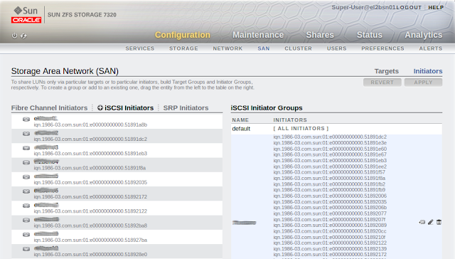
      ZFS Appliance iSCSI Initiators added and included in a group.

      3. Create Storage Project and LUNS

      The final step on the storage server side of things is to create your project & LUNs.   The process to create the project & shares (LUNS in this case) is similar to the process for creating filesystems for use via NFS, as described in an earlier blog posting.  In this case rather than creating a Filesystem though you create a LUN.

      Creating a LUN on the ZFS Storage Appliance
       
      The LUN will now be available to be mounted on any of the compute nodes that are part of the Initiator Group.

      Creating the Solaris Zone on the Shared Storage

      We now have the storage prepared so that it can be mounted on the compute nodes, our intention is to store the zone on the shared storage and setup an additional bonded network on the 10GbE Exalogic client network that the zone will have exclusive access to.

      1. Ensure the disk (LUN) is visible to the node and ready for use.

      The first step we need to take is to ensure that the LUN that was created on the storage device is available to the compute node and that the disk is formatted ready for usage.  Prior to checking for the disk it may be necessary to run the iscsiadm commands to setup the shared storage as a supplier of LUNs.  This should only need to be run once on each compute node but we have found that when all zones are removed from a  node it is necessary to re-run this discovery-address command to make the LUNS visible.

      # iscsiadm add discovery-address <IP of ZFSSA>
      # iscsiadm modify discovery -t enable
      # devfsadm -c iscsi
      # echo | format
      Searching for disks...done


      AVAILABLE DISK SELECTIONS:
             0. c0t600144F09C96CCA90000518CDEB10005d0 <SUN-ZFS Storage 7320-1.0-64.00GB>
                /scsi_vhci/disk@g600144f09c96cca90000518cdeb10005
             1. c0t600144F09C96CCA90000518CDF100006d0 <SUN-ZFS Storage 7320-1.0-64.00GB>
                /scsi_vhci/disk@g600144f09c96cca90000518cdf100006
             2. c0t600144F09C96CCA90000518CDFB60007d0 <SUN-ZFS Storage 7320-1.0-64.00GB>
                /scsi_vhci/disk@g600144f09c96cca90000518cdfb60007
             3. c0t600144F09C96CCA900005190BFC4000Ad0 <SUN-ZFS Storage 7320-1.0 cyl 8352 alt 2 hd 255 sec 63>
                /scsi_vhci/disk@g600144f09c96cca900005190bfc4000a

             4. c7t0d0 <LSI-MR9261-8i-2.12-28.87GB>
                /pci@0,0/pci8086,340a@3/pci1000,9263@0/sd@0,0
      Specify disk (enter its number): Specify disk (enter its number):
      Identifying the LUN on the compute node

       The format command can pick out the LUN which is presented to the Compute Node as a local disk.  The value after the line /scsi_vhci/disk@g maps onto the GUID of the LUN that was created.  This identifies that it is the disk c0t600144F09C96CCA900005190BFC4000Ad0 that is to be formatted and labelled.

      # format -e c0t600144F09C96CCA900005190BFC4000Ad0
      selecting c0t600144F09C96CCA900005190BFC4000Ad0
      [disk formatted]

      FORMAT MENU:
      ...
      format> fdisk
      No fdisk table exists. The default partition for the disk is:

        a 100% "SOLARIS System" partition

      Type "y" to accept the default partition,  otherwise type "n" to edit the
      partition table. n
      SELECT ONE OF THE FOLLOWING:
      ...
      Enter Selection: 1
      Select the partition type to create:
         1=SOLARIS2   2=UNIX      3=PCIXOS     4=Other        5=DOS12
         6=DOS16      7=DOSEXT    8=DOSBIG     9=DOS16LBA     A=x86 Boot
         B=Diagnostic C=FAT32     D=FAT32LBA   E=DOSEXTLBA    F=EFI (Protective)
         G=EFI_SYS    0=Exit? f

      SELECT ONE...
      ...
      6

      format> label
      [0] SMI Label
      [1] EFI Label
      Specify Label type[1]: 1

      Ready to label disk, continue? y

      format> quit

      We can now see that the format command shows the disk as available and now sized as per the LUN size.

      # format
      Searching for disks...done


      AVAILABLE DISK SELECTIONS:
             0. c0t600144F09C96CCA90000518CDEB10005d0 <SUN-ZFS Storage 7320-1.0-64.00GB>
                /scsi_vhci/disk@g600144f09c96cca90000518cdeb10005
             1. c0t600144F09C96CCA90000518CDF100006d0 <SUN-ZFS Storage 7320-1.0-64.00GB>
                /scsi_vhci/disk@g600144f09c96cca90000518cdf100006
             2. c0t600144F09C96CCA90000518CDFB60007d0 <SUN-ZFS Storage 7320-1.0-64.00GB>
                /scsi_vhci/disk@g600144f09c96cca90000518cdfb60007
             3. c0t600144F09C96CCA900005190BFC4000Ad0 <SUN-ZFS Storage 7320-1.0-64.00GB>
                /scsi_vhci/disk@g600144f09c96cca900005190bfc4000a

             4. c7t0d0 <LSI-MR9261-8i-2.12-28.87GB>
                /pci@0,0/pci8086,340a@3/pci1000,9263@0/sd@0,0
      Specify disk (enter its number):

      2. Setup the Networking for Client access.  (10GbE network.)

      The zone that is being setup will be given access to an exclusive IP network, what this means is that we need to create the appropriate VNICs on the global zone and hand control for these VNICs over to the zone to manage.  An earlier blog posting discusses setting up the 10GbE network for Solaris running on an Exalogic and this will build on that knowledge.

      All we need to perform on the global zone is the creation of the VNICs, to do this firstly identify the physical links that relate to the Ethernet over Infiniband devices that the switches present to the Infiniband Host Channel Adapter and hence as devices to the OS.  Then using the two links (one for each physical port) to create the VNICs.

      # dladm show-phys
      LINK              MEDIA                STATE      SPEED  DUPLEX    DEVICE
      net6              Infiniband           up         32000  unknown   ibp1
      net0              Ethernet             up         1000   full      igb0
      net1              Ethernet             unknown    0      unknown   igb1
      net3              Ethernet             unknown    0      unknown   igb3
      net4              Ethernet             up         10     full      usbecm0
      net8              Ethernet             up         10000  full      eoib1
      net2              Ethernet             unknown    0      unknown   igb2
      net5              Infiniband           up         32000  unknown   ibp0
      net9              Ethernet             up         10000  full      eoib0


      One on each link in this case net8 and net9 from above

      # dladm create-vnic -l net8 -v 1706 vnic2_1706
      # dladm create-vnic -l net9 -v 1706 vnic3_1706

      3. Create the Zone

      We now have the prerequisites necessary to create our zone.  (A fairly simple example.)  Namely, the storage available via iSCSI and the VNICs we will hand in to the zone to use.

      # zonecfg -z zone04
      Use 'create' to begin configuring a new zone.
      zonecfg:zone04 create
      create: Using system default template 'SYSdefault'
      zonecfg:zone04> set zonepath=/zones/zone04
      zonecfg:zone04> add rootzpool
      zonecfg:zone04:rootzpool> add storage iscsi://192.168.14.133/luname.naa.600144f09c96cca900005190bfc4000a
      zonecfg:zone04:rootzpool> end
      zonecfg:zone04> remove anet
      zonecfg:zone04> add net
      zonecfg:zone04:net> set physical=vnic2_1706
      zonecfg:zone04:net> end
      zonecfg:zone04> add net
      zonecfg:zone04:net> set physical=vnic3_1706
      zonecfg:zone04:net> end

      zonecfg:zone04> verify
      zonecfg:zone04> commit
      zonecfg:zone04> info
      zonename: zone04
      zonepath: /zones/zone04
      brand: solaris
      autoboot: false
      bootargs:
      file-mac-profile:
      pool:
      limitpriv:
      scheduling-class:
      ip-type: exclusive
      hostid:
      fs-allowed:
      net:
          address not specified
          allowed-address not specified
          configure-allowed-address: true
          physical: vnic2_1706
          defrouter not specified
      net:
          address not specified
          allowed-address not specified
          configure-allowed-address: true
          physical: vnic3_1706
          defrouter not specified
      rootzpool:
          storage: iscsi://192.168.14.133/luname.naa.600144f09c96cca900005190bfc4000a
      zonecfg:zone04>

      During this configuration process we use the default zone creation template which includes a network for the net0 link (1GbE management) which we do not need in our zone so we remove this as part of the configuration.  The storage is defined using the URL for the LUN, this includes the LUN GUID prefixed by iscsi://<IP Address of the Shared Storage>/luname.naa.

      The next step is to install the zone and boot it up.  Before attempting to do this ensure that you have a valid repository for the Solaris installation setup on the global zone.  The zone creation will use this repository to lay down the OS files for the zone. 


      # zoneadm -z zone04 install
      Configured zone storage resource(s) from:
          iscsi://192.168.14.133/luname.naa.600144f09c96cca900005190bfc4000a
      Created zone zpool: zone04_rpool
      Progress being logged to /var/log/zones/zoneadm.20130513T104657Z.zone04.install
             Image: Preparing at /zones/zone04/root.

       AI Manifest: /tmp/manifest.xml.lPaGVo
        SC Profile: /usr/share/auto_install/sc_profiles/enable_sci.xml
          Zonename: zone04
      Installation: Starting ...

                    Creating IPS image
      Startup linked: 1/1 done
                    Installing packages from:
                        exa-family
                            origin:  http://localhost:1008/exa-family/acbd22da328c302a86fb9f23d43f5d10f13cf5a6/
                        solaris
                            origin:  http://install1/release/solaris/
      DOWNLOAD                                PKGS         FILES    XFER (MB)   SPEED
      Completed                            185/185   34345/34345  229.7/229.7 10.6M/s

      PHASE                                          ITEMS
      Installing new actions                   48269/48269
      Updating package state database                 Done
      Updating image state                            Done
      Creating fast lookup database                   Done
      Installation: Succeeded

              Note: Man pages can be obtained by installing pkg:/system/manual

       done.

              Done: Installation completed in 81.509 seconds.


        Next Steps: Boot the zone, then log into the zone console (zlogin -C)

                    to complete the configuration process.

      Log saved in non-global zone as /zones/zone04/root/var/log/zones/zoneadm.20130513T104657Z.zone04.install


      # zoneadm -z zone04 boot

      The zone should boot up very quickly then you can zlogin to the zone to setup the networking.  This will involve using the VNICs given to the zone for exclusive control to create interfaces, bond them together using the Solaris ipmp functionality and allocate an IP address.  We found that we also had to setup the routing table to give a default route.

      # zlogin zone04
      [Connected to zone 'zone04' pts/7]
      Oracle Corporation    SunOS 5.11    11.1    December 2012

      root@zone04:~# dladm show-vnic
      LINK                OVER         SPEED  MACADDRESS        MACADDRTYPE       VID
      vnic2_1706          ?            10000  2:8:20:f5:83:fa   random            1706
      vnic3_1706          ?            10000  2:8:20:fa:ab:98   random            1706
      root@zone04:~# ipadm create-ip vnic2_1706
      root@zone04:~# ipadm create-ip vnic3_1706
      root@zone04:~# ipadm create-ipmp bond1
      root@zone04:~# ipadm add-ipmp -i vnic2_1706 -i vnic3_1706 bond1
      root@zone04:~# ipadm set-ifprop -p standby=on -m ip vnic3_1706
      root@zone04:~# ipadm show-if
      IFNAME     CLASS    STATE    ACTIVE OVER
      lo0        loopback ok       yes    --
      vnic2_1706 ip       ok       yes    --
      vnic3_1706 ip       ok       no     --
      bond1      ipmp     down     no     vnic2_1706 vnic3_1706
      root@zone04:~# ipadm create-addr -T static -a local=138.3.51.2/22 bond1/v4
      root@zone04:~# ipadm show-if
      IFNAME     CLASS    STATE    ACTIVE OVER
      lo0        loopback ok       yes    --
      vnic2_1706 ip       ok       yes    --
      vnic3_1706 ip       ok       no     --
      bond1      ipmp     ok       yes    vnic2_1706 vnic3_1706
      root@zone04:~# ipadm show-addr
      ADDROBJ           TYPE     STATE        ADDR
      lo0/v4            static   ok           127.0.0.1/8
      bond1/v4          static   ok           138.3.51.2/22
      lo0/v6            static   ok           ::1/128
      root@zone04:~# netstat -rn

      Routing Table: IPv4
        Destination           Gateway           Flags  Ref     Use     Interface
      -------------------- -------------------- ----- ----- ---------- ---------
      127.0.0.1            127.0.0.1            UH        2          0 lo0      
      138.3.48.0           138.3.51.2           U         2          0 bond1    

      Routing Table: IPv6
        Destination/Mask            Gateway                   Flags Ref   Use    If  
      --------------------------- --------------------------- ----- --- ------- -----
      ::1                         ::1                         UH      2       0 lo0  
      root@zone04:~# route -p add default 138.3.48.1
      add net default: gateway 138.3.48.1
      add persistent net default: gateway 138.3.48.1
      root@zone04:~# netstat -rn

      Routing Table: IPv4
        Destination           Gateway           Flags  Ref     Use     Interface
      -------------------- -------------------- ----- ----- ---------- ---------
      default              138.3.48.1           UG        1          0          
      127.0.0.1            127.0.0.1            UH        2          0 lo0      
      138.3.48.0           138.3.51.2           U         2          0 bond1    

      Routing Table: IPv6
        Destination/Mask            Gateway                   Flags Ref   Use    If  
      --------------------------- --------------------------- ----- --- ------- -----
      ::1                         ::1                         UH      2       0 lo0  
      root@zone04:~#

      Migrating the Zone from one host to another.

      As a final activity we tried going through the process to see how simple it is to move the zone from one physical host to another.  This approach seems to work smoothly and allowed the zone to be moved in a matter of minutes although it did have to be shutdown during the process. (ie. If you are needing 100% service availability then make sure you use a clustered software solution that will enable continuous availability.)

      Firstly on the compute node that originally hosts the zone shutdown & detatch the zone then export the configuration.  We exported it to a filesystem on the ZFS storage that was mounted on both the original and target hosts (/u01/common/general)   Alternatively the export could be simply scp'd between the nodes.)


      # zoneadm -z zone04 shutdown
      # zoneadm -z zone04 detach
      zoneadm: zone 'zone04': warning(s) occured during processing URI: 'iscsi://192.168.14.133/luname.naa.600144f09c96cca900005190bfc4000a'
      Could not remove one or more iSCSI discovery addresses because logical unit is in use
      Exported zone zpool: zone04_rpool
      Unconfigured zone storage resource(s) from:
              iscsi://192.168.14.133/luname.naa.600144f09c96cca900005190bfc4000a


      # mkdir -p /u01/common/general/zone04
      # zonecfg -z zone04 export > /common/general/zone04/zone04.cfg

      Then on the new zone host we import the zone from the export created on the original host, attach the zone and boot it up.

      # zonecfg -z zone04 -f /common/general/zone04/zone04.cfg
      # zoneadm -z zone04 attach
      Configured zone storage resource(s) from:
          iscsi://192.168.14.133/luname.naa.600144f09c96cca900005190bfc4000a
      Imported zone zpool: zone04_rpool
      Progress being logged to /var/log/zones/zoneadm.20130513T135704Z.zone04.attach
          Installing: Using existing zone boot environment
            Zone BE root dataset: zone04_rpool/rpool/ROOT/solaris
                           Cache: Using /var/pkg/publisher.
        Updating non-global zone: Linking to image /.
      Processing linked: 1/1 done
        Updating non-global zone: Auditing packages.
      No updates necessary for this image.

        Updating non-global zone: Zone updated.
                          Result: Attach Succeeded.
      Log saved in non-global zone as /zones/zone04/root/var/log/zones/zoneadm.20130513T135704Z.zone04.attach

      # zoneadm -z zone04 boot

      The only issue that we identified was that the process of detaching and attaching cause the server to boot up with the system configuration wizard running.   (Logon to the console to complete the wizard - # zlogin -C zone04 This needs to be completed to allow the zone to boot fully.

      Monday, September 10, 2012

      Setting up a local Yum Server using the Exalogic ZFS Storage Appliance

      One of the Exalogic Racks that I have setup had no access to the internet from the 10GbE network, as such no easy mechanism for additional rpms to be deployed to the vServers that are created.  In order to make things simpler for installation on the multiple vServers and have some degree of control over what versions of the software are installed this note describes how to setup a local yum server.
      Within an Exalogic we have a handy HTTP server built into the ZFS storage device which we will use to serve up the content of the YUM Repository. This makes it available to every vServer that is attached to the vServer-shared-storage network.

      Setup the Yum Repository

      This first activity is to setup the actual repository on the shared repository. A few activities are required to enable this:-

      Create a share for the repository

      The first step is to create a share on the Exalogic rack that will be used to host the yum repository and make it available via HTTP. Some instructions on setting up a share can be found in the technote "Creating a Project or Share in the ZFS appliance".  In this case this service will be common to all vServers so use the existing project "common" and create a share under it called "yum-repo", making the share available via HTTP.

      Having created the share we need to make it available via HTTP. To achieve this firstly enable the HTTP service on the ZFS appliance. This is achieved by clicking the enable icon on the HTTP service inside the Configuration/Services tab. The service shown below.


      Having enabled the HTTP service it is then necessary to change the configuration for the share to make the share content available via HTTP. This is achieved by selecting "Shares" then picking the share itself. In our case this is common/yum-repo. Now select the Protocol tab option and set the "Share mode" of the HTTP service to Read Only.  If this is not possible it is probably because it has been set to Inherit from project.  If you are happy to have all shares under the project exposing their content via HTTP then leave the "Inherit from project" option selected and change the HTTP protocol on the project level so that it is set to Read only.  If you only want to expose this share then de-select the "Inherit from project" option and set the share mode to Read only.

      Create the Repository

      The simplest way to get a hold of the appropriate packages is to download the Exalogic base image. This is the .iso file rather than the virtual image which is a single image file as oppose to an installation CD. From the Exalogic e-delivery website it is possible to download the latest physical image. (At the time of writing this was the 2.0.0.0.0 version.) It ships as two zip files which need to be expanded and the runMe.sh run which will amalgamate the two images to create a single iso file.

      Using the single iso file loopback mount the iso and then copy all the content onto the yum-repo share.

      So an example process from a compute node to mount the iso and copy the contents off it is shown below.


      # mkdir /mnt/yum-repo
      # mount <IP address of shared storage>:/export/common/yum-repo /mnt/yum-repo
      # cp <Path to base image>/el_x2-2_baseimage_linux_2.0.0.0.0_64.iso /mnt/yum-repo
      # mkdir /mnt/yum-repo/tmp
      # mount -o loop /mnt/yum-repo/el_x2-2_baseimage_linux_2.0.0.0.0_64.iso /mnt/yum-repo/tmp
      # mkdir /mnt/yum-repo/el_x2-2_baseimage_linux_2.0.0.0.0_64
      # cp -r /mnt/yum-repo/tmp/* /mnt/yum-repo/el_x2-2_baseimage_linux_2.0.0.0.0_64


      Now we want to run the createrepo command to actually create the repository that all the clients can utilise. In order to achieve this the first thing we need to do is actually install the repository package, then run the createrepo command.

      # cd /mnt/yum-repo/el_x2-2_baseimage_linux_2.0.0.0.0_64
      # find . -name createrepo*
      ./Server/createrepo-0.4.11-3.el5.noarch.rpm
      # rpm -ivh /mnt/yum-repo/el_x2-2_baseimage_linux_2.0.0.0.0_64/Server/createrepo-0.4.11-3.el5.noarch.rpm
      warning: /mnt/yum-repo/el_x2-2_baseimage_linux_2.0.0.0.0_64/Server/createrepo-0.4.11-3.el5.noarch.rpm: Header V3 DSA signature: NOKEY, key ID 1e5e0159
      Preparing... ########################################### [100%]
      1:createrepo ########################################### [100%]
      #
      # createrepo .
      3338/3338 - VT/etherboot-roms-kvm-5.4.4-13.el5.x86_64.rpm 6_64.rpm.rpmpm
      Saving Primary metadata
      Saving file lists metadata
      Saving other metadata
      #

      Configure the Client & Install the Packages.

      Now log onto your vServer to configure the yum repository. This is done by creating the file /etc/yum.repos.d/local_yum.repo, the content of which specifies the HTTP address for the yum repository on the shared storage. Once created you can run yum reposlist to ensure that it is configured correctly.yum

      # cat /etc/yum.repos.d/local_yum.repo
      [local_yum]
      name=Exalogic TVP yum rack
      baseurl=http://<IP address of your ZFS Storage appliance on the vServer-shared-storage network (172.17.0.n by default)>/shares/export/common/yum-repo/el_x2-2_baseimage_linux_2.0.0.0.0_64
      gpgcheck=0
      enabled=1

      #
      # yum repolist
      Loaded plugins: rhnplugin, security
      This system is not registered with ULN.
      ULN support will be disabled.
      local_yum | 951 B 00:00
      local_yum/primary | 1.6 MB 00:00
      local_yum 3338/3338
      repo id repo name status
      local_yum Exalogic TVP yum rack enabled: 3,338
      repolist: 3,338
      [root@esat-ldap ~]#

      #

      Then run 'yum repolist' and if everything's is ok you see the repository listed.